ESP8266
|
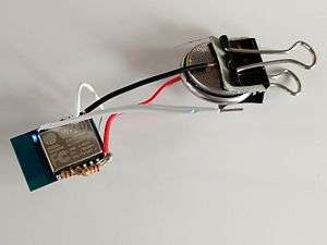
ESP8266 module powered by a coin cell battery | |
| Manufacturer | Espressif |
|---|---|
| Type | Microcontroller |
| CPU | @ 80 (default) or 160 MHz |
| Memory | 64 KiB for instruction and 96 KiB for Data |
| Input | 16 GPIO pins |
| Power | 3.3 V DC |
The ESP8266 is a low-cost Wi-Fi chip with full TCP/IP stack and MCU (Micro Controller Unit) capability produced by Shanghai-based Chinese manufacturer, Espressif Systems.[1]
The chip first came to the attention of western makers in August 2014 with the ESP-01 module, made by a third-party manufacturer, AI-Thinker. This small module allows microcontrollers to connect to a Wi-Fi network and make simple TCP/IP connections using Hayes-style commands. However, at the time there was almost no English-language documentation on the chip and the commands it accepted.[2] The very low price and the fact that there were very few external components on the module which suggests that it could eventually be very inexpensive in volume, attracted many hackers to explore the module, chip, and the software on it, as well as to translate the Chinese documentation.[3]
The ESP8285 is an ESP8266 with 1 MB of built-in flash, allowing for single-chip devices capable of connecting to Wi-Fi.[4]
The successor to these module(s) is ESP32.
Features
- 32-bit RISC CPU: Tensilica Xtensa LX106 running at 80 MHz*
- 64 KiB of instruction RAM, 96 KiB of data RAM
- External QSPI flash - 512 KiB to 4 MiB* (up to 16 MiB is supported)
- IEEE 802.11 b/g/n Wi-Fi
- Integrated TR switch, balun, LNA, power amplifier and matching network
- WEP or WPA/WPA2 authentication, or open networks
- 16 GPIO pins
- SPI, I²C,
- I²S interfaces with DMA (sharing pins with GPIO)
- UART on dedicated pins, plus a transmit-only UART can be enabled on GPIO2
- 1 10-bit ADC
* Both the CPU and flash clock speeds can be doubled by overclocking on some devices. CPU can be run at 160 MHz and flash can be sped up from 40 MHz to 80 MHz. Success varies chip to chip.
SDKs
In late October 2014, Espressif released a software development kit (SDK) that allowed the chip to be programmed, removing the need for a separate microcontroller.[5] Since then, there have been many official SDK releases from Espressif; Espressif maintains two versions of the SDK — one that is based on RTOS and the other based on callbacks.[6]
An alternative to Espressif's official SDK is the open source esp-open-sdk[7] that is based on the GCC toolchain. ESP8266 uses the Cadence Tensilica LX106 microcontroller and the GCC toolchain is open-sourced and maintained by Max Filippov.[8] Another alternative is "Unofficial Development Kit" by Mikhail Grigorev.[9][10]
Other open source SDKs include:
- NodeMCU: a Lua-based firmware.
- Arduino: a C++ based firmware. This core enables the ESP8266 CPU and its Wi-Fi components to be programmed like any other Arduino device. The ESP8266 Arduino Core is available through GitHub.
- MicroPython: a port of the MicroPython (an implementation of Python for embedded devices) to the ESP8266 platform.
- ESP8266 BASIC: An open source basic interpreter specifically tailored for the internet of things. Self hosting browser based development environment.
- Mongoose Firmware: An open source firmware with complimentary cloud service [11]
- + https://github.com/SuperHouse/esp-open-rtos open RTOS.
Espressif modules
This is the series of ESP8266-based modules made by Espressif.
| Name | Active pins | Pitch | Form factor | LEDs | Antenna | Shielded? | Dimensions (mm) | Notes |
|---|---|---|---|---|---|---|---|---|
| ESP-WROOM-02[12] | 18 | 0.1" | 2×9 DIL | No | PCB trace | Yes | 18 × 20 | FCC ID 2AC7Z-ESPWROOM02 |
In the table above (and the two tables which follow), "Active pins" include the GPIO and ADC pins with which you can attach external devices to the ESP8266 MCU. The "Pitch" is the space between pins on the ESP8266 module, which is important to know if you are going to breadboard the device. The "Form factor" also describes the module packaging as "2 x 9 DIL", meaning two rows of 9 pins arranged "Dual In Line", like the pins of DIP ICs. Many ESP-xx modules include a small on-board LED which can be programmed to blink and thereby indicate activity. There are several antenna options for ESP-xx boards including a trace antenna, an on-board ceramic antenna, and an external connector which allows you to attach an external Wi-Fi antenna. Since Wi-Fi communications generates a lot of RFI (Radio Frequency Interference), governmental bodies like the FCC like shielded electronics to minimize interference with other devices. Some of the ESP-xx modules come housed within a metal box with an FCC seal of approval stamped on it. First and second world markets will likely demand FCC approval and shielded Wi-Fi devices.
AI-Thinker modules
.jpg)
These are the first series of modules made with the ESP8266 by the third-party manufacturer AI-Thinker and remain the most widely available.[13] They are collectively referred to as "ESP-xx modules" and to form a workable development system require additional components, especially a serial TTL-to-USB adapter (sometimes called a USB-to-UART bridge) and an external 3.3 Volt power supply. Novice ESP-8266 developers are encouraged to consider larger ESP8266 Wi-Fi development boards like the NodeMCU which includes the USB-to-UART bridge and a Micro-USB connector coupled with a 3.3 Volt power regulator already built into the board. When project development is complete, you may not need these components and can consider using these cheaper ESP-xx modules as a lower power, smaller footprint option for your production runs.
| Name | Active pins | Pitch | Form factor | LEDs | Antenna | Shielded? | dimensions (mm) | Notes |
|---|---|---|---|---|---|---|---|---|
| ESP-01 | 6 | 0.1" | 2×4 DIL | Yes | PCB trace | No | 14.3 × 24.8 | |
| ESP-02 | 6 | 0.1" | 2×4 castellated | No | U-FL connector | No | 14.2 × 14.2 | |
| ESP-03 | 10 | 2 mm | 2×7 castellated | No | Ceramic | No | 17.3 × 12.1 | |
| ESP-04 | 10 | 2 mm | 2×4 castellated | No | None | No | 14.7 × 12.1 | |
| ESP-05 | 3 | 0.1" | 1×5 SIL | No | U-FL connector | No | 14.2 × 14.2 | |
| ESP-06 | 11 | misc | 4×3 dice | No | None | Yes | 14.2 × 14.7 | Not FCC approved |
| ESP-07 | 14 | 2 mm | 2×8 pinhole | Yes | Ceramic + U-FL connector | Yes | 20.0 × 16.0 | Not FCC approved |
| ESP-08 | 10 | 2 mm | 2×7 castellated | No | None | Yes | 17.0 × 16.0 | Not FCC approved |
| ESP-09 | 10 | misc | 4×3 dice | No | None | No | 10.0 × 10.0 | |
| ESP-10 | 3 | 2 mm? | 1×5 castellated | No | None | No | 14.2 × 10.0 | |
| ESP-11 | 6 | 0.05" | 1×8 pinhole | No | Ceramic | No | 17.3 × 12.1 | |
| ESP-12 | 14 | 2 mm | 2×8 castellated | Yes | PCB trace | Yes | 24.0 × 16.0 | FCC and CE approved[14] |
| ESP-12E | 20 | 2 mm | 2×8 castellated | Yes | PCB trace | Yes | 24.0 × 16.0 | 4 MB Flash |
| ESP-12F | 20 | 2 mm | 2×8 castellated | Yes | PCB trace | Yes | 24.0 × 16.0 | FCC and CE approved. Improved antenna performance. 4 MB Flash |
| ESP-13 | 16 | 1.5 mm | 2×9 castellated | No | PCB trace | Yes | W18.0 x L20.0 | Marked as ″FCC″. Shielded module is placed sideways, as compared to the ESP-12 modules. |
| ESP-14 | 22 | 2 mm | 2×8 castellated +6 | No | PCB trace | Yes | 24.3 x 16.2 |
Other boards
The popularity of many of these "other boards" over the earlier ESP-xx modules is the inclusion of an on-board USB-to-UART bridge (like the Silicon Labs' CP2102 or the WHC CH340G) and a Micro-USB connector coupled with a 3.3 Volt regulator to provide both power to the board and connectivity to the host (software development) computer commonly referred to as the console. With earlier ESP-xx modules, these two items (the USB-to-Serial adaptor and a 3.3 Volt regulator) had to be purchased separately and be wired into the ESP-xx circuit. Modern ESP8266 boards like the NodeMCU boards are a lot less painful and offer more GPIO pins to play with. Most of these "other boards" are based on the ESP-12E module, but new modules are being introduced seemingly every few months.
| Name | Active pins | Pitch | Form factor | LEDs | Antenna | Shielded? | dimensions (mm) | Notes |
|---|---|---|---|---|---|---|---|---|
| Bolt IoT | 14 | 0.1" | 2×14 DIL | Yes | PCB trace | Yes | 30 × 40 | Comes with an on Board SD card and technologies like Lib-Discovery and Fail Safe Mode. Has its own cloud for IoT. |
| Olimex MOD-WIFI-ESP8266[15] | 2 | 0.1" | UEXT module | Yes | PCB trace | No | ? | Only RX/TX are connected to UEXT connector |
| Olimex MOD-WIFI-ESP8266-DEV[16] | 20 | 0.1" | 2×11 DIL + castellated | Yes | PCB trace | No | ? | All available GPIO pins are connected, also has pads for soldering UEXT connector (with RX/TX and SDA/SCL signals) |
| NodeMCU DEVKIT | 14 | 0.1" | 2×15 DIL | Yes | PCB trace | Yes | ? | Uses the ESP-12 module, includes USB serial interface |
| Adafruit Huzzah ESP8266 breakout[17] | 14 | 0.1" | 2×10 DIL | Yes | PCB trace | Yes | 25 × 38 | Uses the ESP-12 module |
| SparkFun ESP8266 Thing[18] WRL-13231 | 12 | 0.1" | 2×10 DIL | Yes | PCB trace + U.FL socket | No | 58 × 26 | FTDI serial header, Micro-USB socket for power, includes Li-ion battery charger |
| KNEWRON Technologies smartWIFI[19] | 12 | 0.1" | 2×20 DIL | Yes 1 RGB | PCB trace | Yes | 25.4 × 50.8 | CP2102 USB bridge, includes battery charger, micro-USB socket for power and battery charging, 1 RGB LED and USER / Reflash button |
| WeMos D1[20] | 12 | 0.1" | Arduino Uno | Yes | PCB trace | Yes | 53.4 × 68.6 | Uses the ESP-12F module, Micro-USB socket |
| WeMos D1 R2[21] | 12 | 0.1" | Arduino Uno | Yes | PCB trace | Yes | 53.4 × 68.6 | Uses the ESP-12F module, Micro-USB socket |
| WeMos D1 Mini[22] | 12 | 0.1" | 2×8 DIL | Yes | PCB trace | Yes | 25.6 × 34.2 | Uses the ESP-12F module, Micro-USB socket |
| ESPert ESPresso Lite[23] | 16 | 0.1" | 2×8 DIL | Yes | PCB trace | Yes | 26.5 × 57.6 | Uses the WROOM-02 module. Produced in limited quantity as beta version. |
| ESPert ESPresso Lite V2.0[24] | 24 | 0.1" | 2×10 DIL | Yes | PCB trace | Yes | 28 × 61 | Improved design and feature to ESPresso Lite. |
| In-Circuit ESP-ADC[25] | 18 | 0.1" | 2×9 DIL | No | U.FL socket | No | 22.9 × 14.9 | Uses the ESP8266EX |
| Watterott ESP-WROOM02-Breakout[26] | 14 | 0.1" | 2×10 DIL | Yes | PCB trace | Yes | 40.64 × 27.94 | Uses the Espressif ESP-WROOM-02 module. |
See also
References
- ↑ Linux and Open Source Hardware for IoT
- ↑ Brian Benchoff (August 26, 2014). "New Chip Alert: The ESP8266 WiFi Module (It's $5)". hackaday. Retrieved 2015-06-24.
- ↑ Brian Benchoff (September 6, 2014). "The Current State of ESP8266 Development". hackaday. Retrieved 2015-06-24.
- ↑ "Espressif Announces ESP8285 Wi-Fi Chip for Wearable Devices". Espressif. Mar 9, 2016. Retrieved 2016-07-10.
- ↑ Brian Benchoff (October 25, 2014). "An SDK for the ESP8266 WiFi Chip". hackaday. Retrieved 2015-06-24.
- ↑ Espressif Systems (July 29, 2015). "Official SDK release from Espressif for ESP8266". Espressif. Retrieved 2015-08-08.
- ↑ https://github.com/pfalcon/esp-open-sdk
- ↑ Max Filippov (Feb 15, 2015). "ESP8266 GCC Toolchain". Retrieved 2015-08-08.
- ↑ https://github.com/CHERTS/esp8266-devkit>
- ↑ http://programs74.ru/udkew-en.html
- ↑ https://mongoose-iot.com/docs/#/quickstart/
- ↑ "Espressif ESP-WROOM-02". Espressif Inc. Retrieved 2015-07-29.
- ↑ "ESP8266 module family". esp8266.com wiki. Retrieved 2015-06-24.
- ↑ "2ADUIESP-12 by Shenzhen Anxinke technology co., LTD for Wi-Fi Module". FCC. December 30, 2014. Retrieved 2015-06-24.
- ↑ "MOD-WIFI-ESP8266". Olimex. Retrieved 2015-06-25.
- ↑ "MOD-WIFI-ESP8266-DEV". Olimex. Retrieved 2015-06-25.
- ↑ "Adafruit HUZZAH ESP8266 Breakout". Adafruit Industries. Retrieved 2015-06-25.
- ↑ "SparkFun ESP8266 Thing". SparkFun. Retrieved 2015-06-27.
- ↑ "KNEWRON smartWIFI". KNEWRON. Retrieved 2016-03-04.
- ↑ "WeMos D1". WeMos. Retrieved 2016-11-30.
- ↑ "WeMos D1 R2". WeMos. Retrieved 2016-01-05.
- ↑ "WeMos D1 Mini". WeMos. Retrieved 2016-11-30.
- ↑ "Espert". Espert. Retrieved 2016-01-07.
- ↑ "Cytron Technologies - ESPresso Lite V2.0". www.cytron.com.my. Retrieved 2016-02-10.
- ↑ "ESP-ADC DIL18 development board". In-Circuit Wiki. Retrieved 2016-02-03.
- ↑ "Watterott ESP-WROOM02-Breakout". Watterott. Retrieved 2016-11-06.
External links
- BBS.espressif.com — Espressif's forum with complete documentation on the ESP8266
- ESP8266.com — Community forum
- WiFi-IoT — Universal firmware WEB-builder from Maxim Miklin. The firmware is written in pure C language.
- RuntimeProjects.com - Tutorials on how to use ESP8266 with Arduino Core.
- Blog with ESP8266 projects — Blog with a lot of projects like MQTT broker on ESP8266, Control Air Conditioner, Irrigation, LoRa
- How to flash ESP8266 — How to flash an ESP8266 with custom NodeMCU firmware
| Wikimedia Commons has media related to ESP8266. |