Furnace

A furnace is a device used for high-temperature heating. The name derives from Greek word fornax, which means oven.
In American English and Canadian English usage, the term furnace on its own refers to the household heating systems based on a central furnace (known either as a boiler, or a heater in British English), and sometimes as a synonym for kiln, a device used in the production of ceramics. In British English, a furnace is an industrial furnace used for many things, such as the extraction of metal from ore (smelting) or in oil refineries and other chemical plants, for example as the heat source for fractional distillation columns.
The term furnace can also refer to a direct fired heater, used in boiler applications in chemical industries or for providing heat to chemical reactions for processes like cracking, and is part of the standard English names for many metallurgical furnaces worldwide.
The heat energy to fuel a furnace may be supplied directly by fuel combustion, by electricity such as the electric arc furnace, or through induction heating in induction furnaces.
Large furnaces

A large furnace is a major appliance that is permanently installed to provide heat to an interior space through intermediary fluid movement, which may be air, steam, or hot water. Heating appliances that use steam or hot water as the fluid are normally referred to as a residential steam boiler or residential hot water boiler. The most common fuel source for modern furnaces in North America and much of Europe is natural gas; other common fuel sources include LPG (liquefied petroleum gas), fuel oil and in rare cases coal or wood. In some areas electrical resistance heating is used, especially where the cost of electricity is low or the primary purpose is for air conditioning.
Modern high-efficiency furnaces can be 98% efficient and operate without a chimney. The small amount of waste gas and heat are mechanically ventilated through PVC pipes that can be vented through the side or roof of the house. Fuel efficiency in a gas furnace is measured in AFUE (Annual Fuel Utilization Efficiency).
Categories
Residential furnaces can be classified into four general categories, based on efficiency and design.
Natural draft
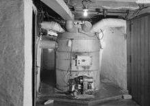
The first category would be natural draft, atmospheric burner furnaces. These furnaces consisted of cast-iron or riveted-steel heat exchangers built within an outer shell of brick, masonry, or steel. The heat exchangers were vented through brick or masonry chimneys. Air circulation depended on large, upwardly pitched pipes constructed of wood or metal The pipes would channel the warm air into floor or wall vents inside the home. This method of heating worked because warm air rises. The system was simple, had few controls, a single automatic gas valve, and no blower. These furnaces could be made to work with any fuel simply by adapting the burner area. They have been operated with wood, coke, coal, trash, paper, natural gas, and fuel oil. Furnaces that used solid fuels required daily maintenance to remove ash and "clinkers" that accumulated in the bottom of the burner area. In later years, these furnaces were adapted with electric blowers to aid air distribution and speed moving heat into the home. Gas and oil-fired systems were usually controlled by a thermostat inside the home, while most wood and coal-fired furnaces had no electrical connection and were controlled by the amount of fuel in the burner and position of the fresh-air damper on the burner access door.
Forced-air
The second category of residential furnace is the forced-air, atmospheric burner style with a cast-iron or sectional steel heat exchanger. Through the 1950s and 1960s, this style of furnace was used to replace the big, natural draft systems, and was sometimes installed on the existing gravity duct work. The heated air was moved by blowers which were belt driven and designed for a wide range of speeds. These furnaces were still big and bulky compared to modern furnaces, and had heavy-steel exteriors with bolt-on removable panels. Energy efficiency would range anywhere from just over 50% to upward of 65% AFUE. This style furnace still used large, masonry or brick chimneys for flues and was eventually designed to accommodate air-conditioning systems.
Forced draft
The third category of furnace is the forced draft, mid-efficiency furnace with a steel heat exchanger and multi-speed blower. These furnaces were physically much more compact than the previous styles. They were equipped with combustion air blowers that would pull air through the heat exchanger which greatly increased fuel efficiency while allowing the heat exchangers to become smaller. These furnace may have multi-speed blowers and were designed to work with central air-conditioning systems.
Condensing
The fourth category of furnace is the high-efficiency, or condensing furnace. High-efficiency furnaces can achieve from 89% to 98% fuel efficiency. This style of furnace includes a sealed combustion area, combustion draft inducer and a secondary heat exchanger. Because the heat exchanger removes most of the heat from the exhaust gas, it actually condenses water vapor and other chemicals (which form a mild acid) as it operates. The vent pipes are normally installed with PVC pipe versus metal vent pipe to prevent corrosion. The draft inducer allows for the exhaust piping to be routed vertically or horizontally as it exits the structure. The most efficient arrangement for high-efficiency furnaces include PVC piping that brings fresh combustion air from the outside of the home directly to the furnace. Normally the combustion air (fresh air) PVC is routed alongside the exhaust PVC during installation and the pipes exit through a sidewall of the home in the same location. High efficiency furnaces typically deliver a 25% to 35% fuel savings over a 60% AFUE furnace.
Heat distribution
The furnace transfers heat to the living space of the building through an intermediary distribution system. If the distribution is through hot water (or other fluid) or through steam, then the furnace is more commonly called a boiler. One advantage of a boiler is that the furnace can provide hot water for bathing and washing dishes, rather than requiring a separate water heater. One disadvantage to this type of application is when the boiler breaks down, neither heating nor domestic hot water are available.
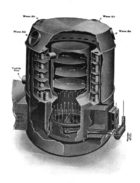
Air convection heating systems have been in use for over a century, but the older systems relied on a passive air circulation system where the greater density of cooler air caused it to sink into the furnace, and the lesser density of the warmed air caused it to rise in the ductwork, the two forces acting together to drive air circulation in a system termed "gravity-feed" the layout of the ducts and furnace was optimized for short, large ducts. This caused the furnace to be referred to as an "octopus" furnace.
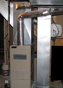
By comparison, most modern "warm air" furnaces typically use a fan to circulate air to the rooms of house and pull cooler air back to the furnace for reheating; this is called forced-air heat. Because the fan easily overcomes the resistance of the ductwork, the arrangement of ducts can be far more flexible than the octopus of old. In American practice, separate ducts collect cool air to be returned to the furnace. At the furnace, cool air passes into the furnace, usually through an air filter, through the blower, then through the heat exchanger of the furnace, whence it is blown throughout the building. One major advantage of this type of system is that it also enables easy installation of central air conditioning, simply by adding a cooling coil at the outlet of the furnace.
Air is circulated through ductwork, which may be made of sheet metal or plastic "flex" duct, and is insulated or uninsulated. Unless the ducts and plenum have been sealed using mastic or foil duct tape, the ductwork is likely to have a high leakage of conditioned air, possibly into unconditioned spaces. Another cause of wasted energy is the installation of ductwork in unheated areas, such as attics and crawl spaces; or ductwork of air conditioning systems in attics in warm climates.
Furnace types
Single-stage
A single-stage furnace has only one stage of operation, it is either on or off. This means that it is relatively noisy, always running at the highest speed, and always pumping out the hottest air at the highest velocity.
One of the benefits to a single-stage furnace is typically the cost for installation. Single-stage furnaces are relatively inexpensive since the technology is rather simple.
Two-stage
This type has two stages of operation, full speed and half (or reduced) speed. Depending on the demanded heat, they can run at a lower speed most of the time. They can be quieter, move the air at less velocity, and will better keep the desired temperature in the house.
Modulating
This type of furnace can modulate the heat output and air velocity nearly continuously, depending on the demanded heat and outside temperature. This means that it only works as much as necessary and therefore saves energy.
Possible failures
The following rare but difficult-to-diagnose failure can occur. If the temperature inside the furnace exceeds a maximum threshold, a safety mechanism with a thermostat will shut the furnace down. A symptom of this failure is that the furnace repeatedly shuts down before the house reaches the desired temperature; this is commonly referred to as the furnace "riding the high limit switch". This condition commonly occurs if the temperature setting of the high limit thermostat is set too close to the normal operating temperature of the furnace. Another situation may occur if a humidifier is incorrectly installed on the furnace and the duct which directs a portion of the humidified air back into the furnace is too large. The solution is to reduce the diameter of the cross-feed tube, or install a baffle that reduces the volume of re-fed air.
Metallurgical furnaces

In metallurgy, several specialized furnaces are used. These include:
- Furnaces used in smelters, including:
- The blast furnace, used to reduce iron ore to pig iron
- Steelmaking furnaces, including:
- Furnaces used to remelt metal in foundries.
- Furnaces used to reheat and heat treat metal for use in:
- Rolling mills, including tinplate works and slitting mills.
- Forges.
- Vacuum furnaces
Industrial process furnaces

An industrial furnace or direct fired heater, is an equipment used to provide heat for a process or can serve as reactor which provides heats of reaction. Furnace designs vary as to its function, heating duty, type of fuel and method of introducing combustion air. However, most process furnaces have some common features.
Fuel flows into the burner and is burnt with air provided from an air blower. There can be more than one burner in a particular furnace which can be arranged in cells which heat a particular set of tubes. Burners can also be floor mounted, wall mounted or roof mounted depending on design. The flames heat up the tubes, which in turn heat the fluid inside in the first part of the furnace known as the radiant section or firebox. In this chamber where combustion takes place, the heat is transferred mainly by radiation to tubes around the fire in the chamber. The heating fluid passes through the tubes and is thus heated to the desired temperature. The gases from the combustion are known as flue gas. After the flue gas leaves the firebox, most furnace designs include a convection section where more heat is recovered before venting to the atmosphere through the flue gas stack. (HTF=Heat Transfer Fluid. Industries commonly use their furnaces to heat a secondary fluid with special additives like anti-rust and high heat transfer efficiency. This heated fluid is then circulated round the whole plant to heat exchangers to be used wherever heat is needed instead of directly heating the product line as the product or material may be volatile or prone to cracking at the furnace temperature.)
Radiant section

The radiant section is where the tubes receive almost all its heat by radiation from the flame. In a vertical, cylindrical furnace, the tubes are vertical. Tubes can be vertical or horizontal, placed along the refractory wall, in the middle, etc., or arranged in cells. Studs are used to hold the insulation together and on the wall of the furnace. They are placed about 1 ft (300 mm) apart in this picture of the inside of a furnace. The tubes, shown below, which are reddish brown from corrosion, are carbon steel tubes and run the height of the radiant section. The tubes are a distance away from the insulation so radiation can be reflected to the back of the tubes to maintain a uniform tube wall temperature. Tube guides at the top, middle and bottom hold the tubes in place.
Convection section

The convection section is located above the radiant section where it is cooler to recover additional heat. Heat transfer takes place by convection here, and the tubes are finned to increase heat transfer. The first two tube rows in the bottom of the convection section and at the top of the radiant section is an area of bare tubes (without fins) and are known as the shield section ("shock tubes"), so named because they are still exposed to plenty of radiation from the firebox and they also act to shield the convection section tubes, which are normally of less resistant material from the high temperatures in the firebox. The area of the radiant section just before flue gas enters the shield section and into the convection section called the bridgezone. A crossover is the tube that connects from the convection section outlet to the radiant section inlet. The crossover piping is normally located outside so that the temperature can be monitored and the efficiency of the convection section can be calculated. The sightglass at the top allows personnel to see the flame shape and pattern from above and visually inspect if flame impingement is occurring. Flame impingement happens when the flame touches the tubes and causes small isolated spots of very high temperature.
Radiant coil
This is a series of tubes horizontal/ vertical hairpin type connected at ends (with 180° bends) or helical in construction. The radiant coil absorbs heat through radiation. They can be single pass or multi pass depending upon the process-side pressure drop allowed. The radiant coils and bends are housed in the radiant box. Radiant coil materials vary from carbon steel for low temperature services to high alloy steels for high temperature services. These are supported from the radiant side walls or hanging from the radiant roof. Material of these supports is generally high alloy steel. While designing the radiant coil, care is taken so that provision for expansion (in hot conditions) is kept.
Burner

The burner in the vertical, cylindrical furnace as above, is located in the floor and fires upward. Some furnaces have side fired burners, such as in train locomotives. The burner tile is made of high temperature refractory and is where the flame is contained. Air registers located below the burner and at the outlet of the air blower are devices with movable flaps or vanes that control the shape and pattern of the flame, whether it spreads out or even swirls around. Flames should not spread out too much, as this will cause flame impingement. Air registers can be classified as primary, secondary and if applicable, tertiary, depending on when their air is introduced. The primary air register supplies primary air, which is the first to be introduced in the burner. Secondary air is added to supplement primary air. Burners may include a pre-mixer to mix the air and fuel for better combustion before introducing into the burner. Some burners even use steam as premix to preheat the air and create better mixing of the fuel and heated air. The floor of the furnace is mostly made of a different material from that of the wall, typically hard castable refractory to allow technicians to walk on its floor during maintenance.
A furnace can be lit by a small pilot flame or in some older models, by hand. Most pilot flames nowadays are lit by an ignition transformer (much like a car's spark plugs). The pilot flame in turn lights up the main flame. The pilot flame uses natural gas while the main flame can use both diesel and natural gas. When using liquid fuels, an atomizer is used, otherwise, the liquid fuel will simply pour onto the furnace floor and become a hazard. Using a pilot flame for lighting the furnace increases safety and ease compared to using a manual ignition method (like a match).
Sootblower
Sootblowers are found in the convection section. As this section is above the radiant section and air movement is slower because of the fins, soot tends to accumulate here. Sootblowing is normally done when the efficiency of the convection section is decreased. This can be calculated by looking at the temperature change from the crossover piping and at the convection section exit.
Sootblowers utilize flowing media such as water, air or steam to remove deposits from the tubes. This is typically done during maintenance with the air blower turned on. There are several different types of sootblowers used. Wall blowers of the rotary type are mounted on furnace walls protruding between the convection tubes. The lances are connected to a steam source with holes drilled into it at intervals along its length. When it is turned on, it rotates and blows the soot off the tubes and out through the stack.
Stack

The flue gas stack is a cylindrical structure at the top of all the heat transfer chambers. The breeching directly below it collects the flue gas and brings it up high into the atmosphere where it will not endanger personnel.
The stack damper contained within works like a butterfly valve and regulates draft (pressure difference between air intake and air exit) in the furnace, which is what pulls the flue gas through the convection section. The stack damper also regulates the heat lost through the stack. As the damper closes, the amount of heat escaping the furnace through the stack decreases, but the pressure or draft in the furnace increases which poses risks to those working around it if there are air leakages in the furnace, the flames can then escape out of the firebox or even explode if the pressure is too great.
Insulation
Insulation is an important part of the furnace because it improves efficiency by minimizing heat escape from the heated chamber. Refractory materials such as firebrick, castable refractories and ceramic fibre, are used for insulation. The floor of the furnace are normally castable type refractories while those on the walls are nailed or glued in place. Ceramic fibre is commonly used for the roof and wall of the furnace and is graded by its density and then its maximum temperature rating. For example, 8# 2,300 °F means 8 lb/ft3 density with a maximum temperature rating of 2,300 °F. The actual service temperature rating for ceramic fiber is a bit lower than the maximum rated temperature. (i.e. 2300 °F is only good to 2145 °F before permanent linear shrinkage).
Foundations
Concrete pillars are foundation on which the heater is mounted. They can be four nos. for smaller heaters and may be up to 24 nos. for large size heaters. Design of pillars and entire foundation is done based on the load bearing capacity of soil and seismic conditions prevailing in the area. Foundation bolts are grouted in foundation after installation of the heater.
Access doors
The heater body is provided with access doors at various locations. Access doors are to be used only during shutdown of heater. The normal size of the access door is 600x400 mm, which is sufficient for movement of men/ material into and out of the heater. During operation the access doors are properly bolted using leak proof high temperature gaskets.
See also
Notes
References
- Gray, W.A.; Muller, R (1974). Engineering calculations in radiative heat transfer (1st ed.). Pergamon Press Ltd. ISBN 0-08-017786-7.
- Fiveland, W.A., Crosbie, A.L., Smith A.M. and Smith, T.F. (Editors) (1991). Fundamentals of radiation heat transfer. American Society of Mechanical Engineers. ISBN 0-7918-0729-0.
- Warring, R. H (1982). Handbook of valves, piping and pipelines (1st ed.). Gulf Publishing Company. ISBN 0-87201-885-7.
- Dukelow, Samuel G (1985). Improving boiler efficiency (2nd ed.). Instrument Society of America. ISBN 0-87664-852-9.
- Whitehouse, R.C. (Editor) (1993). The valve and actuator user's manual. Mechanical Engineering Publications. ISBN 0-85298-805-2.
- Davies, Clive (1970). Calculations in furnace technology (1st ed.). Pergamon Press. ISBN 0-08-013366-5.
- Goldstick, R.; Thumann, A (1986). Principles of waste heat recovery. Fairmont Press. ISBN 0-88173-015-7.
- ASHRAE (1992). ASHRAE Handbook. Heating, ventilating and air-conditioning systems and equipment. ASHRAE. ISBN 0-910110-80-8. ISSN 1078-6066.
- Perry, R.H. and Green, D.W. (Editors) (1997). Perry's Chemical Engineers' Handbook (7th ed.). McGraw-Hill. ISBN 0-07-049841-5.
- Lieberman, P.; Lieberman, Elizabeth T (2003). Working Guide to Process Equipment (2nd ed.). McGraw-Hill. ISBN 0-07-139087-1.
External links
| Wikimedia Commons has media related to Furnace. |