Joule thief

A joule thief is a minimalist Armstrong[1] self-oscillating voltage booster that is small, low-cost, and easy to build, typically used for driving small loads. This circuit is also known by other names such as joule ringer or blocking oscillator.
It can use nearly all of the energy in a single-cell electric battery, even far below the voltage where other circuits consider the battery fully discharged (or "dead"); hence the name, which suggests the notion that the circuit is stealing energy or "joules" from the source. The term is a pun on the expression "jewel thief": one who steals jewelry or gemstones.
The circuit is a variant of the blocking oscillator that forms an unregulated voltage boost converter. The output voltage is increased at the expense of higher current draw on the input, but the integrated (average) current of the output is lowered and brightness of a luminescence decreased.
History
In the November 1999 issue of Everyday Practical Electronics (EPE) magazine, the "Ingenuity Unlimited" (reader ideas) section had a novel circuit idea entitled "One Volt LED - A Bright Light" by Z. Kaparnik from Swindon, Wilts, UK. Three example circuits were shown for operating LEDs from supply voltages below 1.5 Volts. The basic circuits consisted of a transformer-feedback ZTX450 NPN transistor voltage converter based on the blocking oscillator, which originally used a vacuum tube or thermionic valve and dates prior to World War II.[2]
In 2002,[3] the name "Joule Thief" was coined by Clive Mitchell[4][5] and given to his variant of Kaparnik's circuit which consisted of a single cell, a single BC549 NPN transistor, a coil with two windings, a single resistor (typically 1000 ohms), and a single white LED. Clive originally named the circuit "Vampire Torch", because it sucked the last remnants of life from a battery.
Mitchell's newer circuit is essentially the same as Kaparnik's older circuit, except for component values:
- The Kaparnik schematic showed a resistor value of 10K though he stated that lower resistance, such as 2K, would produce higher currents; where as Mitchell's schematic showed only a 1K resistor in his schematic.
- Kaparnik stated that an NPN transistor with lower Vce(sat) yielded better results. He tested three transistors: ZTX450 at 73% efficiency, ZTX650 at 79% efficiency, BC550 at 57% efficiency. Mitchell showed only the BC549 in his schematic.
A capacitor connected to the base and across the battery have been added here. If using a third inductor it may also increase voltage. Travis b. Moore made an odd joule thief circuit using this configuration running a NPN transistor and TIP 31-like transistor in a Darlington pair using a single AAA cell. The 1200 µF cap was placed across the battery and a 10 pf cap to the base. A third inductor from a power supply was added to increase voltage. Then another joule thief built with a single transistor was about 80% efficient to 90%.[6][7]
Prior art
The joule thief is not a new concept. It basically adds an LED on the output of an old idea.
- US Patent 1949383,[8] filed in 1930, "Electronic device", describes a vacuum tube based oscillator circuit to convert a low voltage into a high voltage.
- US Patent 2211852,[9] filed in 1937, "Blocking oscillator apparatus", describes a vacuum tube based blocking oscillator.
- US Patent 2745012,[10] filed in 1951, "Transistor blocking oscillators", describes three versions of a transistor based blocking oscillator.
- US Patent 2780767,[11] filed in 1955, "Circuit arrangement for converting a low voltage into a high direct voltage".
- US Patent 2881380,[12] filed in 1956, "Voltage converter".
- US Patent 4734658,[13] filed in 1987, "Low voltage driven oscillator circuit", describes a very low voltage driven oscillator circuit, capable of operating from as little as 0.1 volts. This is a far lower voltage than that at which the joule thief will operate. This is achieved by using a JFET, which does not require the forward biasing of a PN junction for its operation, because it is used in the depletion mode. In other words, the drain–source already conducts, even when no bias voltage is applied. The '658 patent is intended for use with thermoelectric power sources, which are inherently low-voltage devices.
Description of operation
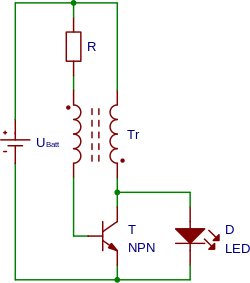
The circuit works by rapidly switching the transistor. Initially, current begins to flow through the resistor, secondary winding, and base-emitter junction (see diagram) which causes the transistor to begin conducting collector current through the primary winding. Since the two windings are connected in opposing directions, this induces a voltage in the secondary winding which is positive (due to the winding polarity, see dot convention) which turns the transistor on with higher bias. This self-stroking/positive-feedback process almost instantly turns the transistor on as hard as possible (putting it in the saturation region), making the collector-emitter path look like essentially a closed switch (since VCE will be only about 0.1 volts, assuming that the base current is high enough). With the primary winding effectively across the battery, the current increases at a rate proportional to the supply voltage divided by the inductance. Transistor switch-off takes place by different mechanisms dependent upon supply voltage.
At lower supply voltages a different mode of operation takes over: the gain of a transistor is not linear with VCE. At low supply voltages (typically 0.75 V and below) the transistor requires a larger base current to maintain saturation as the collector current increases. Hence, when it reaches a critical collector current, the base drive available becomes insufficient and the transistor starts to pinch off and the previously described positive feedback action occurs turning it hard off.
To summarize, once the current in the coils stops increasing for any reason, the transistor goes into the cutoff region (and opens the collector-emitter "switch"). The magnetic field collapses, inducing however much voltage is necessary to make the load conduct, or for the secondary-winding current to find some other path.
When the field is back to zero, the whole sequence repeats; with the battery ramping-up the primary-winding current until the transistor switches on.
If the load on the circuit is very small the rate of rise and ultimate voltage at the collector is limited only by stray capacitances, and may rise to more than 100 times the supply voltage. For this reason, it is imperative that a load is always connected so that the transistor is not damaged. Because VCE is mirrored back to the secondary, failure of the transistor due to a small load will occur through the reverse VBE limit for the transistor being exceeded (this occurs at a much lower value than VCEmax).
The transistor dissipates very little energy, even at high oscillating frequencies, because it spends most of its time in the fully on or fully off state, so either voltage over or current through the transistor is zero, thus minimizing the switching losses.
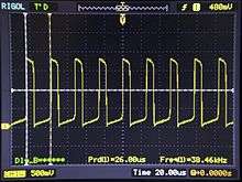
The switching frequency in the example circuit opposite is about 50 kHz. The light-emitting diode will blink at this rate, but the persistence of the human eye means that the blinking will not be noticed.[4]
Regulated voltage

A simple modification of the previous schematic replaces the LED with three components to create a simple zener diode based voltage regulator. A better solution is shown in the next schematic example.

When a more constant output voltage is desired, the Joule Thief can be given a closed-loop control. In the example circuit, the Schottky diode D1 blocks the charge built up on capacitor C1 from flowing back to the switching transistor Q1 when it is turned on. A 5.6 Volt Zener diode D2 and transistor Q2 forms the feedback control: when the voltage across the capacitor C1 is higher than the threshold voltage formed by Zener voltage of D2 plus the base-emitter turn-on voltage of transistor Q2, transistor Q2 is turned on diverting the base current of the switching transistor Q1, impeding the oscillation and prevents the voltage across capacitor C1 from rising even further. When the voltage across C1 drops below the threshold voltage Q2 turns off, allowing the oscillation to happen again. If the load requires even lower ripple, in this example some delicate digital circuitry like a microcontroller, a linear regulator can be used after this to smooth the ripple out.
See also
- Armstrong oscillator
- Blocking oscillator
- Flyback converter
- Forward converter
- Switched-mode power supply
References
- ↑ "Fun Examples for Teaching Linear and Nonlinear Circuits", Circuits and Systems (ISCAS), 2013 IEEE International Symposium on, 19–23 May 2013, p2557 - 2560
- ↑ Everday Practical Electronics; November 1999.
- ↑ 2002 archive of "Make a joule thief" webpage
- 1 2 3 "Make a joule thief". Retrieved 28 June 2013.
- ↑ "Clive's YouTube channel". Retrieved 20 September 2015.
- ↑ http://rustybolt.info/wordpress/wp-content/uploads/2011/12/JT-ConvSuperchgd2-172x300.gif
- ↑ http://rustybolt.info/wordpress/?p=221
- ↑ google.com/patents: "Electronic device", filed 13 Feb 1930, retrieved 16 Aug 2016
- ↑ google.com/patents: "Blocking oscillator apparatus", filed 22 Jan 1937, retrieved 16 Aug 2016
- ↑ google.com/patents: "Transistor blocking oscillators", filed 18 Aug 1951, retrieved 16 Aug 2016
- ↑ google.com/patents: "Circuit arrangement for converting a low voltage into a high direct voltage", filed 7 Apr 1955, retrieved 16 Aug 2016
- ↑ google.com/patents: "Voltage converter", filed 15 Oct 1956, retrieved 16 Aug 2016
- ↑ google.com/patents: "Low voltage driven oscillator circuit", filed 14 Aug 1987, retrieved 20 March 2012
External links
| Wikimedia Commons has media related to Joule thief (electronics). |
- Simulations and implementations
- Joule Thief Simulation
- Simulation and efficiency comparison of different Joule Thief versions (Polish)
- Supercharged Joule Thief Has High Efficiency
- Joule Thief - Modified Version
- Video
- Other