Locks on the Chesapeake and Ohio Canal

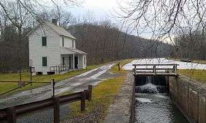
The Locks on the Chesapeake and Ohio Canal, located in Maryland, West Virginia, and Washington, D.C. of the United States, were of three types: lift locks; river locks; and guard, or inlet, locks.
They were numbered from 1 to 75, including two locks with fractional numbers (63⅓ and 64⅔) and none numbered 65. There is also the Tidewater Lock, sometimes called Lock 0, lock at the downstream end of the canal in Washington, D.C., where Rock Creek flows into the Potomac River.
The fractionally numbering arose because locks 70-75 were completed in 1842, before locks 62 and 66.[1] It was found that the level of the canal between locks 62 and 66 could be raised in three steps instead of four. So the additional locks through there were numbered 1⅓ steps apart (62, 63⅓, 64⅔ and 66) so that the other locks, already completed, did not have to be renumbered.
While the "Frequently Asked Questions" website published by the National Park Service states that it takes about 10 minutes for a boat to lock through,[2] experiments done in the 1830s show that it was possible for a boat to go through in 2½ minutes, although 3 minutes was their average.[3] In 1897 it was shown that steamboats took 5 to 7 minutes to lock through whether going upstream or downstream (respectively).[4]
Guard locks
Since these were locks to regulate water coming into the canal, they are frequently called inlet locks. At the slackwaters (particularly at Big Slackwater and Little Slackwater) they allowed boats to reenter the canal from the slackwater. There is no guard lock #7, since Dam #7 was proposed to be around mile 164 near the mouth of South Branch, but it was never built. A steam pump was later put where this dam would have been in 1856.[5] In 1872, a new steam pump was put 10 miles upstream at mile 174.2, and gave about 24 cubic feet per second of water.[6]
The first guard lock was made of structures from George Washington's Potomac Company Little Falls skirting canal, and were repurposed for the C&O.[7]
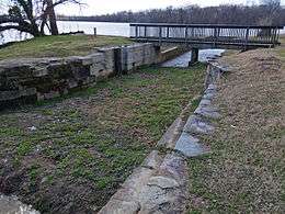
The second guard lock at Violette's lock, was confusingly numbered Lock 24 for a period of time when that was the end of the canal. Later, when the section up to Dam #3 (Harpers Ferry) was opened, Lock 24 was the lock at the Seneca Aqueduct (i.e. Riley's Lock). Guard lock #2 is also 88' 5" long, making it too small for a standard C & O canal boat (92') to go through.[8]
| Lock | Miles | Name | Nearby landmarks | Coordinates | Date | Photo |
|---|---|---|---|---|---|---|
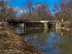
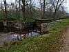
| 1 | 4 | Guard Lock #1 | Consists of 2 gates: a feeder and guard gate. | 38°56′23″N 77°07′20″W / 38.939847°N 77.122232°W | c. 1795 |  |
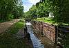
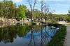
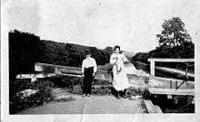
| 2 | 22 | Guard Lock #2 | Violette's lock | 39°04′01″N 77°19′44″W / 39.06694°N 77.328851°W | Nov 1830 |  |
| 3 | 62 | Guard Lock #3 | Above Harpers Ferry | 39°20′10″N 77°45′07″W / 39.33623478012774°N 77.75199501711157°W | Sept 1833 | 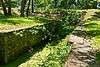 |
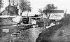
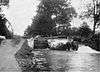
| 4 | 85.4 | Guard Lock #4 | Big Slackwater | 39°30′11″N 77°50′42″W / 39.503118°N 77.845039°W | Apr 1834 |  |
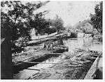
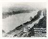
| 5 | 106.8 | Guard Lock #5 | Little Slackwater | 39°36′26″N 77°55′20″W / 39.607337°N 77.92211°W | Jan 1835 |  |
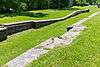
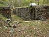
| 6 | 134 | Guard Lock #6 | 39°37′29″N 78°17′30″W / 39.62482639486258°N 78.29161104978726°W | Oct 1838 |  | |
| 7 | 164 | Not built | ||||
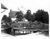
| 8 | 184.5 | Guard Lock #8 | End of Canal, Cumberland MD | 39°38′54″N 78°45′50″W / 39.648353°N 78.763884°W | May 1850 |  |
River Locks
There were three sets of river locks (not counting the guard locks) which were used for traffic coming from Virginia.
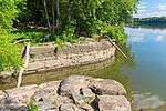
The Goose Creek locks were 0.2 miles below Edwards Ferry (Lock 25), in section 51 used for traffic coming from Goose Creek on the Virginia shore.[7] It allowed boats from the Goose Creek and Little River Navigation Company to enter. Only one Goose Creek boat was documented to enter the C&O canal, and there is no documentation of a C&O boat entering Goose Creek. The lock was eventually converted into a waste weir.[9] The Goose Creek lock is actually a staircase lock or combine lock [10] (perhaps the only one on the C & O canal), i.e. two locks are put together with no intervening pound or basin between them, the upper gate of the lower lock being the same gate as the lower gate of the second lock.
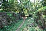
The Shenendoah river locks (section 109), were across from Harper's Ferry, just below Lock 33 at the Shenandoah River.[7] This lock let boats cross to Harpers Ferry with the mules walking on the railroad bridge, up the Shenandoah river, to the old Potomac Canal Bypass on the Shenandoah river by Virginius island. The railroad refused to let mules walk on the bridge, and from lack of business, the lock was abandoned. Stones from that lock were used for other purposes.[11]
The Shepherdstown river lock (section 133) was served by a dam for Botler's mill on the Virginia Side. After the 1889 flood destroyed the dam, the slackwater from that dam was gone, and the reason for the existence of that lock vanished, and it was later filled in and used for the towpath.[12]
Lift Locks

There were several different variations with the 74 lift locks. Note also that a boat going the whole length of the canal would also have to go through 2 guard locks as well (at Big Slackwater and Little Slackwater respectively).[13]
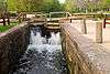
Locks were typically 100 feet long, 15 feet wide, and 16 feet deep, and the lifts averaged about 8 feet (between 6 and 10).[14] Inside dimensions of the lock, for the boat, are over 90', for instance Lock 28 (Point of Rocks) is 90' 9", whereas typical freight boats were 92' long (including the rudder), making it necessary to turn the rudder to the side to fit in the lock.[15] Lock 36, however, was known among boatmen for being troublesome, since it had a usable length of 89 feet 11 inches, being the only lock less than 90 feet in length.[16] Locks were often whitewashed to facilitate low light (i.e., at dawn or dusk) visibility.[17]
Lock foundation was 12" x 12" timbers, spaced about a foot apart, laid longitudinally below the walls, overlain by traverse timbers, also 12" x 12". These in turn were overlain with 3 inch planks, with the masonry placed upon them. All timbers were intended to be permanently wet.[18]
During construction, the builders left room on the berm side, should another lock be constructed alongside, but such never happened.[19][20]
Debris which got into the lock sometimes had to be removed with a pitchfork.[21] If the paddle valve was stuck because of trash, the lock tender had a 20-foot poll with a hook to get the trash free.[22]
Lock numbering changed over the years. As mentioned before, Guard Lock No. 2 was numbered Lock 24 for a time, which could cause confusion with Riley's Lock, No 24, upstream.[8] For a period of time in the early days, the locks were called by letters but that was later changed to numbers.[23] Oddly enough, many of the lock numbers correspond to the contour elevation, e.g. Lock 26 is at the 260 foot elevation line, and lock 30 is at the 300 foot mark, although it is doubted that things were planned that way, and many locks do not correspond to the elevation, e.g. Lock 72 is at the 580 foot mark.[23]
Lock Design

There were two designs used on the C&O Canal locks: the 1828 design and the 1830 design. Locks 1-27 (with the exception of lock 13) are to the older 1828 design, and locks 13 and 28-75 are of the 1830 design.[15]
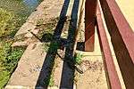
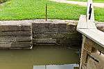
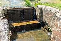
The 1828 design originally filled the lock chamber through the use of culverts in the lock masonry. The wicket, i.e. large paddle valve, hidden in the masonry recess where the upper gate fit in, would be opened, and water would flow through the lock masonry to three openings in the lock chamber. Both sides of the lock had these, so there would be a total of 2 wickets, and 6 openings. The upper gate is above the breast wall.[24][25] Most of the wicket openings in the upper gate recess have been closed with masonry, but one wicket at Violettes Lock is still intact as of 2013 (see photo). Note that modern replacement gates in locks 1-23, have the wickets in the gates, since the original wickets in the lock masonry are inoperable. This system of routing water through the masonry was abandoned due the tendency for debris to clog the opening.[26]

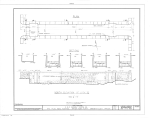
The 1830 design eliminated the use of culverts in the masonry, and the upper gate is below the breast wall.[25] The advantage here is that the lock can fill faster with the wickets being in the gate, but will not swamp a boat in the lock chamber. In the 1830 design locks, the upper and lower gates are both the same height.[15] The majority of locks on the C&O canal are to this specification.
Having the wickets in the gates, particularly if the gates are above the breast wall, means that the water pouring in could swamp some boats in the lock. Filling the lock through culverts eliminated that problem, as well as putting the lock gate below the breast wall.
Lock 27 is a curious combination of the two specifications, having the culverts inside the masonry, but the upper gate below the breast wall. This is because of multiple contractors working on the lock after a lapse of time.[27]

Most locks were fitted with V gates, but some locks, particularly around Seven Locks (7, 9, 10, and 12), and also all three North Branch locks (Locks 73–75 [28][29] ), were re-fitted with mechanical drop gates to speed up traffic in those areas. (Note that lock 6 had been converted to a drop gate, and later converted back to a V gate.[30]) With the mechanical locks, a lever pulls a rod which connects to a crank, connected to another rod which turned the wicket valve which was in the floor (below where the gate would rest when opened) and water flows below the floor and into the lock. Hahn states this brought the time to lock through from about 10 minutes to around 3 minutes.[20]
Lock Cramps
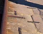
There were three different periods (or kinds) of iron cramps (like staples) to hold the lock stones together. First is 1/2" x 1 1/2" 13 inches long, later 1/2" x 2" 13" to 14" long, and late, 1" round iron, and 1/2" into the stone.[31]
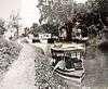
Double locks
In 1875, the company decided to experiment with double boats (one boat tied to another, pulled by a team of mules) allowing them to decrease freight costs by 50%.[32][33] The company extended 14 locks to do so. Locks 25 through 32 were extended for that reason. 11 locks were extended at the lower end (like Lock 25) and 3 were extended at the upper end, for a total of 14 extended locks on the canal. While since that time the stones from the downstream extensions have often been removed, the early mule rise (i.e. the towpath rise before the lock appears 120 feet earlier than normal) indicates the locks extended at the lower end.[34] Lander Lock (No. 29) is a good example of this.[35] While physical evidence shows that locks 25, 27, 29–33, 37, 38, 43, & 60 also were lengthened, Canal records only mention locks 5-7 being lengthened [36]
In May 1864, those who tended these double locks wanted higher pay for them, but were unsuccessful. As a result, one of the lockkeepers, S. C. Rogers, abandoned his post (Locks 45 – 46) in protest, and was replaced by Obadiah Barger.[37] Later in November 1864, Obadiah complained that he had been removed as locktender of the same locks (45-46) without just cause, and the locktender Susan Newcomer was never present but hired a youth without approval of the company, to tend the locks. After an investigation showed it to be true, she was sacked and Obadiah was reinstated as locktender again.[38]
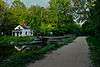
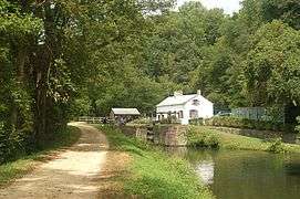
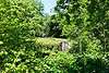
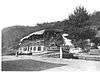
Lock tender's Shanty
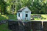
It was quite common to build a little shanty so that the lockkeeper could look for boats coming, especially during the night or inclement weather.
Increase in depth
Some locks were increased in depth (Lock 25, 22, etc. for instance) by bolting timbers to the top of the lock. Some of those bolts are still in the stonework. This was apparently done because of silting in the canal necessitating raising the water level.[39]
Bypass flumes
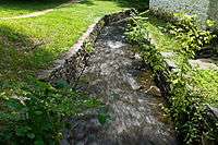
Most locks have a bypass flume, which allows water to bypass the lock to water the level below. If the flume was covered over with concrete, that generally meant that a roadway passed over the lock.[40] Originally the locks 1-27, with the possible exception of Lock 13 did not have bypass flumes, using the culverts to divert water, but later the bypass flumes were put in (which is what we see today).[41]
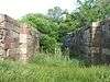
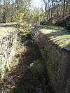
Composite Locks

Locks 58-71 are composite locks. Because there was a scarcity of good building stone in the upper Potomac, they made those locks of rubble and undressed inferior stone. Since the stone was undressed, that made a rougher surface, so the interior of the lock had to be lined with wood so as not to damage the boats in the lock. The wood sheathing had to be replaced from time to time.[42] Originally kyanized wood was used.[43]
Ellwood Morris, the Assistant Engineer, suggested using cement instead of stone for the locks to cut cost.[44] On September 25, 1938, Charles B Fisk, the chief engineer, wrote to the board recommending the use of composite locks, such as those already found on the Chenango Canal.[45] Chief Engineer Charles Fisk was the one who prevailed on the board of directors to remove Lock 65.[46] This resulted in the numbering of fractional locks 63⅓ and 64⅔, so that the numbering above Lock 65 (now eliminated) could be preserved.
On 1 June 1870, Engineer W R Hunton reported that the composite locks were serviceable but not in good condition, with coping out of place, and leaks due to lack of mortar. Some of the locks were rebuilt in 1873-74.[47]
By 1886-1888 the locks were in bad shape and in need of repair or rebuilding. Around 1910, because of problems, the wood was replaced with cement (which is often what is seen today). Some of that was because it was impractical to line the gate pockets with wood.[48]
Locks 66, 64⅔ and 63⅓ have a 10-foot lift instead of the regulation 8 foot lift.
Lock names
Some of the locks were also informally named, usually after a prominent lockkeeper, a nearby town or important geographical feature. Some locks are known by more than one name and some are only known by their number. The names of the lockkeepers changed over the years, and the nicknames also changed. For instance Lock 21 had many lockkeepers: Mr. Fuller (1830), Mrs Susan Cross (1836), Robert C Fields (1839, Fired on 1 May 1846), Samuel Fisher (1846, 1851),[3] and Jesse Swain (1924),[49] hence today the lock is known as "Swain's Lock". The Swain family had been involved with the canal ever since its construction: John Swain helped build the canal; his sons John, Hen, and Bill Swain were boatmen as well as Jesse Swain (boatman and later locksman), and his son, Otho Swain.[50]
Darbey's lock or Darkey's lock was named after Hughey Darkey, who had four or five red-headed girls.[51]
Twigg's lock (69) was named after the Twigg family, one of the first settlers in the upper Potomac. John and Rebecca Twigg who settled there in the mid 1700s had two sons, Robert and Fleetwood John Twigg because of whom a Romeo and Juliet like story (without the tragedy at the end) ensued. Fleetwood John got himself an Indian maiden, and was rejected, so he built his house on the "other side of the pond". The "Blue Eyed Twiggs" (Robert's children) were not allowed to play with "Black Eyed Twiggs" (descended from F. John), and the feud continued for a few generations until a "Blue Eyed Twigg" fell in love with a "Black Eyed Twigg".[52]
Many of the locktenders who were of good reputation, were later promoted to district superintendent. These included Elgin and John Y. Young in the 1830s and 1840s, John Lambie in the 1840s. A. K. Stake began at locks 41–41 from 1847–1848, Lewis G. Stanhop at locks 41–42 also in 1848, and Overton G. Lowe at Lock 56 when the canal opened to Cumberland — these three individuals were later promoted and continued working for the Canal company well into the 1870s.[53]
Incidents
There were plenty of incidents with negligent lockkeepers. On September 11, 1895 at Lock 22, the boat Excelsior arrived, and tried to lock through. The lockkeeper was so drunk, he opened the lower gate paddles too early. The boat hit the mitre sill, broke in half, and sank with its 113 tons of coal. Richard A. Moore, the owner of the boat, collected over $1,300 in damages, and the lockkeeper was fired.[54]
List of Locks
The date is the date when the lock was completed. It often took a year to build the lock, and about $10,000. The lift (in feet) of a lock is listed when known. The locks ranged from 6 foot lift to a 10-foot lift, 8 foot being the most common.[55] Specific information about lock dimensions, materials used, design, etc. can be found in William Davies's book.[16]


Stop Gates
There were a number of stop gates throughout the canal, e.g. between lock 16 and lock 17, on section 17. For some reason, the list Unrau has does not list that lock. The others are listed by section number along the canal, but he did not provide a list of where the section numbers correspond to mileage numbers along the canal. Note that the greatest number of stop gates were between Lock 50 and 51, that is the 14 mile level which includes Big Pool. There are stop gates both before and after Big pool.
To add to the confusion, some of the locks, such as lock 33, had provisions to put in boards as a stop gate at the top of the lock. Lift locks with such provisions are not listed here.
| Section | Miles | Nearby landmarks | Coordinates | Date | Photo |
|---|---|---|---|---|---|
| C | 2.18 | Georgetown. Visible when water is low.[65] | April 1837 | ||
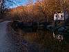
| 17 | 13.7 | Great Falls. | 38°59′36″N 77°14′43″W / 38.993271°N 77.245146°W | 1852[66] | 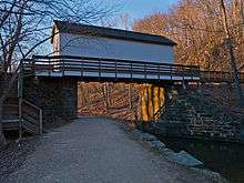 |
| 38 | 24 | Was between Locks 24 and 25.[67] Davies reported "There are no remains of it"[68] | March 1836 | ||
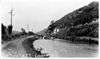
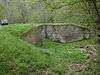
| 156 | 84.4 | At Dam #4 | 39°29′45″N 77°49′36″W / 39.495795°N 77.826631°W | April 1839 | 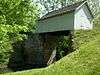 |
| 195 | 102.5 | Was between Locks 44 and 45.[69] Davies reports "No evidence of it remains today"[70] | May 1835 | ||
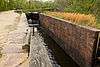
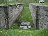
| 209 | 110.29 | Above Lock 50 | June 1839 |  | |
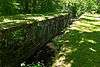
| 213 | 112 | Between locks 50 and 51
Below Big Pool |
39°36′20″N 78°00′18″W / 39.605482°N 78.005044°W | July 1838 | 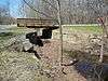 |
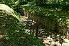
| 217 | 114.15 | Between locks 50 and 51
Above Big Pool |
Feb 1839 |  | |
| 228 | 119.71 | Between locks 50 and 51 | June 1839 | 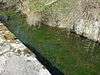 | |
See also
References
- ↑ Edwin C. Bearss. "The Composite Locks" (PDF). [US Department of the Interior, National Park Service]. Retrieved 2013-05-24. p.20
- ↑ Frequently Asked Questions, National Park Service
- 1 2 Unrau, Harlan D. (2007). Historic Resource Study: Chesapeake & Ohio Canal (PDF). Hagerstown, Md.: U.S. Department of the Interior, National Park Service, Chesapeake & Ohio Canal National Historical Park. p. 333. LCCN 2007473571.
- ↑ http://candocanal.org/histdocs/Double_Boat_Report.pdf
- ↑ Unrau p. 208 footnote, 470
- ↑ Hahn, Thomas F. Swiftwater (1993). Towpath Guide to the C&O Canal: Georgetown Tidelock to Cumberland, Revised Combined Edition. Shepherdstown, WV: American Canal and Transportation Center. ISBN 0-933788-66-5. p. 215
- 1 2 3 Unrau p. 238
- 1 2 Hahn, Towpath Guide, p. 51
- ↑ Hahn, Towpath Guide p. 62-63
- ↑ Hahn, Towpath Guide, p. 63.
- ↑ Hahn, Towpath Guide p. 99-100
- ↑ Unrau p. 167, 238
- ↑ Hahn, Thomas F. Swiftwater (1980). The C & O Canal Boatmen, 1892–1924. Shepherdstown, WV: American Canal and Transportation Center. p. 54-56
- ↑ Kytle, Elizabeth (1983). Home on the Canal. Cabin John, MD: Seven Locks Press. ISBN 978-080185328-9., p.68
- 1 2 3 Hahn, Towpath Guide, p. 85
- 1 2 Davies, William E. (1999). The Geology and Engineering Structures of the Chesapeake and Ohio Canal: An Engineering Geologist’s Descriptions and Drawings (PDF). Glen Echo, Md.: C&O Canal Association. Retrieved 2014-07-18.
- ↑ Kytle, p. 138
- ↑ Davies, p. xii
- ↑ Kytle, p. 73
- 1 2 Hahn, Towpath Guide, p. 28
- ↑ Kytle p. 138
- ↑ Kytle p. 206
- 1 2 Weinholt, Ellwood F. Interpretive Material on the Chesapeake and Ohio Canal. National Park Service. p. 30.
- ↑ Hahn, Towpath Guide, p. 47, 48
- 1 2 http://www.nps.gov/history/history/online_books/choh/composite.pdf p. 71
- ↑ Hahn, Pathway, p. 186
- ↑ Hahn, Towpath Guide, p. 75
- ↑ Hahn, Towpath Guide, p. 216
- ↑ http://www.hscl.cr.nps.gov/insidenps/report.asp?STATE=&PARK=CHOH&STRUCTURE=&SORT=&RECORDNO=1097
- ↑ Hahn, Towpath Guide, p. 26
- ↑ Hahn, Towpath Guide p. 32
- ↑ Unrau p. 360
- ↑ Kytle, p. 73-74
- ↑ Hahn, Towpath Guide, p. 64
- ↑ http://www.hscl.cr.nps.gov/insidenps/report.asp?STATE=&PARK=CHOH&STRUCTURE=&SORT=&RECORDNO=319
- ↑ Unrau, Harland. Historic Structure Report, Historical Data, The Masonry Locks, Chesapeake and Ohio Canal National Historical Park, National Park Service, June, 1978
- ↑ Unrau p. 800
- ↑ Unrau p. 801
- ↑ Hahn p. 64
- ↑ Hahn, Towpath Guide p. 85
- ↑ "C&O Canal Association: A Lock is not Just a Lock". . Retrieved 2014-01-06. External link in
|publisher=(help) - ↑ Kytle, Elizabeth. Home on the Canal, P 71-72.
- ↑ Bearss p. 33
- ↑ Bearss, p. 13
- ↑ Bearss, p. 15
- ↑ Bearss, p. 34
- ↑ Bearss, pp. 80-81
- ↑ Bearss, p. 81
- ↑ Kathy Sholl, "Swains Lock Concession Closes," April 27, 2006, National Park Service
- ↑ Kytle p. 129
- ↑ Kytle P.
- ↑ Hahn, Towpath Guide, p. 210-211
- ↑ Unrau p. 803
- ↑ Unrau p. 799
- ↑ Hahn, Towpath, p. 10
- ↑ http://www.hscl.cr.nps.gov/insidenps/report.asp?STATE=&PARK=CHOH&STRUCTURE=&SORT=&RECORDNO=61
- ↑ http://www.hscl.cr.nps.gov/insidenps/report.asp?STATE=&PARK=CHOH&STRUCTURE=&SORT=&RECORDNO=85
- ↑ http://www.hscl.cr.nps.gov/insidenps/report.asp?STATE=&PARK=CHOH&STRUCTURE=&SORT=&RECORDNO=88
- ↑ http://www.hscl.cr.nps.gov/insidenps/report.asp?STATE=&PARK=CHOH&STRUCTURE=&SORT=&RECORDNO=94
- 1 2 According to NPS (http://www.hscl.cr.nps.gov/insidenps/report.asp?STATE=&PARK=CHOH&STRUCTURE=&SORT=&RECORDNO=98) the locks in seven locks go up 56 feet; that means evenly divided, each lock is 8 foot lift
- ↑ Davis notes say "9?" written by hand, on p. 245
- ↑ Davies notes, appears to be 6 feet, on p. 254
- ↑ Unrau notes construction started on this lock in 1836, but in 1839, abandoned construction with lock 40% complete. It was then resumed in 1847, along with other locks, hence the strange completion dates.
- ↑ Hahn, Towpath p.215
- ↑ Hahn, Towpath Guide P. 19
- ↑ Hahn, Towpath Guide, p. 40
- ↑ Unrau, p. 249
- ↑ Davies, p. 118
- ↑ Unrau p. 249–250
- ↑ Davies p. 311
External links
| Wikimedia Commons has media related to Chesapeake & Ohio Canal National Historical Park. |
- A Virtual Tour of the C&O Canal
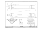
- Historic American Engineering Record (HAER) No. MD-27, "Chesapeake & Ohio Canal, Lock 33 Complex, Mile 60.7, Sharpsburg, Washington County, MD", 2 measured drawings
- HAER No. MD-27-A, "Chesapeake & Ohio Canal, Lock No. 32, Mile 60.7, Sharpsburg, Washington County, MD", 1 photo, 1 measured drawing
- HAER No. MD-30, "Chesapeake & Ohio Canal, Locks 63 1/3, 64 2/3, & 66, State Route 51, Town Creek, Allegany County, MD", 1 measured drawing