Membrane
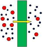
A membrane is a selective barrier; it allows some things to pass through but stops others. Such things may be molecules, ions, or other small particles. Biological membranes include cell membranes (outer coverings of cells or organelles that allow passage of certain constituents);[1] nuclear membranes, which cover a cell nucleus; and tissue membranes, such as mucosae and serosae. Synthetic membranes are made by humans for use in laboratories and industry (such as chemical plants). The influent of an artificial membrane is known as the feed-stream, the liquid that passes through the membrane is known as the permeate, and the liquid containing the retained constituents is the retentate or concentrate.
This concept of a membrane has been known since the eighteenth century, but was used little outside of the laboratory until the end of World War II. Drinking water supplies in Europe had been compromised by the war and membrane filters were used to test for water safety. However, due to the lack of reliability, slow operation, reduced selectivity and elevated costs, membranes were not widely exploited. The first use of membranes on a large scale was with micro-filtration and ultra-filtration technologies. Since the 1980s, these separation processes, along with electrodialysis, are employed in large plants and, today, a number of experienced companies serve the market.[2]
The degree of selectivity of a membrane depends on the membrane pore size. Depending on the pore size, they can be classified as microfiltration (MF), ultrafiltration (UF), nanofiltration (NF) and reverse osmosis (RO) membranes. Membranes can also be of various thickness, with homogeneous or heterogeneous structure. Membranes can be neutral or charged, and particle transport can be active or passive. The latter can be facilitated by pressure, concentration, chemical or electrical gradients of the membrane process. Membranes can be generally classified into synthetic membranes and biological membranes.[3]
Membrane processes classification
Microfiltration (MF)
Microfiltration removes particles higher than 0,08-2 µm and operates within a range of 7-100 kPa.[4] Microfiltration is used to remove residual suspended solids (SS), to remove bacteria in order to condition the water for effective disinfection and as a pre-treatment step for reverse osmosis.
Relatively recent developments are membrane bioreactors (MBR) which combine microfiltration and a bioreactor for biological treatment.
Ultrafiltration (UF)
Ultrafiltration removes particles higher than 0,005-2 µm and operates within a range of 70-700kPa.[4] Ultrafiltration is used for many of the same applications as microfiltration. Some ultrafiltration membranes have also been used to remove dissolved compounds with high molecular weight, such as proteins and carbohydrates. In addition, they are able to remove viruses and some endotoxins.
Nanofiltration (NF)
Nanofiltration is also known as “loose” RO and can reject particles smaller than 0,001 µm. Nanofiltration is used for the removal of selected dissolved constituents from wastewater. NF is primarily developed as a membrane softening process which offers an alternative to chemical softening.
Likewise, nanofiltration can be used as a pre-treatment before directed reverse osmosis. The main objectives of NF pre-treatment are:[5] (1). minimize particulate and microbial fouling of the RO membranes by removal of turbidity and bacteria, (2) prevent scaling by removal of the hardness ions, (3) lower the operating pressure of the RO process by reducing the feed-water total dissolved solids (TDS) concentration.
Reverse osmosis (RO)
Reverse osmosis is commonly used for desalination. As well, RO is commonly used for the removal of dissolved constituents from wastewater remaining after advanced treatment with microfiltration. RO excludes ions but requires high pressures to produce deionized water (850-7000 kPa).
Membrane configurations
In the membrane field, the term module is used to describe a complete unit composed of the membranes, the pressure support structure, the feed inlet, the outlet permeate and retentate streams, and an overall support structure. The principal types of membrane modules are:
- Tubular, where membranes are placed inside a support porous tubes, and these tubes are placed together in a cylindrical shell to form the unit module. Tubular devices are primarily used in micro and ultra filtration applications because of their ability to handle process streams with high solids and high viscosity properties, as well as for their relative ease of cleaning.
- Hollow fiber membrane, consists of a bundle of hundreds to thousands of hollow fibers. The entire assembly is inserted into a pressure vessel. The feed can be applied to the inside of the fiber (inside-out flow) or the outside of the fiber (outside-in flow).
- Spiral Wound, where a flexible permeate spacer is placed between two flat membranes sheet. A flexible feed spacer is added and the flat sheets are rolled into a circular configuration.
- Plate and frame consist of a series of flat membrane sheets and support plates. The water to be treated passes between the membranes of two adjacent membrane assemblies. The plate supports the membranes and provides a channel for the permeate to flow out of the unit module.
- Ceramic and polymeric Flat Sheet Membranes and modules. Flat sheet membranes are typically built-into a submerged vacuum driven filtration systems which consist of stacks of modules each with a number of sheets. Filtration mode is outside-in where the water passes through the membrane and is collected in permeate channels. Cleaning can be performed by aeration, back wash and CIP.
Membrane process operation
The key elements of any membrane process relate to the influence of the following parameters on the overall permeate flux are:
- The membrane permeability (k)
- The operational driving force per unit membrane area (Trans Membrane Pressure, TMP)
- The fouling and subsequent cleaning of the membrane surface.
Flux, pressure, permeability
The total permeate flow from a membrane system is given by following equation:

Where Qp is the permeate stream flowrate [kg·s−1], Fw is the water flux rate [kg·m−2·s−1] and A is the membrane area [m2]
The permeability (k) [m·s−2·bar−1] of a membrane is given by the next equation:

The transmembrane pressure (TMP) is given by the following expression:

where PTMP is the Transmembrane Pressure [kPa], Pf the inlet pressure of feed stream [kPa]; Pc the pressure of concentrate stream [kPa]; Pp the pressure if permeate stream [kPa].
The rejection (r) could be defined as the amount of particles that have been removed from the feedwater.

The corresponding mass balance equations are:


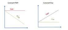
In order to control the operation of a membrane process, two modes, with respect to the flux and to the TMP (Trans Membrane Pressure), can be used. These modes are: (1) constant TMP and (2) constant flux.
The operation modes will be affected when the rejected materials and particles in the retentate tend to accumulate in the membrane. At a given TMP, the flux of water through the membrane will decrease and at a given flux, the TMP will increase, reducing the permeability (k). This phenomenon is known as fouling, and it is the main limitation to membrane process operation.
Dead-end and cross-flow operation modes
Two operation modes for membranes can be used. These modes are:
- Dead end filtration where all the feed applied to the membrane passes through it, obtaining a permeate. Since there is no concentrate stream, all the particles are retained in the membrane. Raw feed-water is sometimes used to flush the accumulated material from the membrane surface.[6]
- Cross-flow filtration where the feed water is pumped with a cross flow tangential to the membrane and a concentrate and permeate streams are obtained. This model implies that for a flow of feed-water across the membrane, only a fraction is converted to permeate product. This parameter is termed “conversion” or “recovery” (S). The recovery will be reduced if the permeate is further used for maintaining processes operation, usually for membrane cleaning.

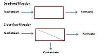 Schematic process of dead-end and cross-flow filtration
Filtration leads to an increase of the resistance against the flow. In the case of dead-end filtration process, the resistance increases according to the thickness of the cake formed on the membrane. As a consequence, the permeability (k) and the flux rapidly decrease, proportionally to the solids concentration and, thus, requiring a periodic cleaning.
For cross-flow processes, the deposition of material will continue until the forces of the binding cake to the membrane will be balanced by the forces of the fluid. At this point, cross-flow filtration will reach a steady-state condition , and thus, the flux will remain constant with time. Therefore, this configuration will demand less periodic cleaning.
Fouling
Fouling can be defined as the potential deposition and accumulation of constituents in the feed stream on the membrane.
Fouling can take place through a number of physicochemical and biological mechanisms which are related to the increase deposition of solid material onto the membrane surface. The main mechanisms by which fouling can occur, are:
- Build-up of constituents of the feedwater on the membrane which causes a resistance to flow. This build-up can be divided into different types:
- Pore narrowing, which consists of solid material that it has been attached to the interior surface of the pores.
- Pore blocking occurs when the particles of the feed-water become stuck in the pores of the membrane.
- Gel/cake layer formation takes places when the solid matter in the feed is larger than the pore sizes of the membrane.
- Formation of chemical precipitates known as scaling
- Colonization of the membrane or biofouling takes place when microorganisms grow on the membrane surface.
Fouling control and mitigation
Since fouling is an important consideration in the design and operation of membrane systems, as it affects pre-treatment needs, cleaning requirements, operating conditions, cost and performance, it should prevented, and if necessary, removed. Optimizing the operation conditions is important to prevent fouling. However, if fouling has already taken place, it should be removed by using physical or chemical cleaning.
Physical cleaning techniques for membrane include membrane relaxation and membrane backwashing.
- Back-washing or back-flushing consist of pumping the permeate in the reverse direction through the membrane. Back-washing removes successfully most of the reversible fouling caused by pore blocking. Backwashing can also be enhanced by flushing air through the membrane.[7] Backwashing increase the operating costs since energy is required to achieve a pressure suitable for permeate flow reversion.
- Membrane relaxation consists of pausing the filtration during a period of time, and thus, there is no need for permeate flow reversion. Relaxation allows filtration to be maintained for longer period of time before the chemical cleaning of the membrane.
Chemical cleaning. Relaxation and backwashing effectiveness will decrease with operation time as more irreversible fouling accumulates on the membrane surface. Therefore, besides the physical cleaning, chemical cleaning may also be recommended. They include:
- Chemical enhanced backwash, that is, a low concentration of chemical cleaning agent is added during the backwashing period.
- Chemical cleaning, where the main cleaning agents are sodium hypochlorite (for organic fouling) and citric acid (for inorganic fouling). It should be point out, though, that every membrane supplier proposes their own chemical cleaning recipes, which differ mainly in terms of concentration and methods.[10]
Optimizing the operation condition. Several mechanisms can be carried out to optimize the operation conditions of the membrane to prevent fouling, for instance:
- Reducing flux. The flux always reduces fouling but obviously it impacts on capital cost since it demands more membrane area. It consists of working at sustainable flux which can be defined as the flux for which the TMP increases gradually at an acceptable rate, such that chemical cleaning is not necessary.
- Using cross-flow filtration instead of dead-end. In cross-flow filtration only a thin layer is deposited on the membrane since not all the particles are retained on the membrane, but the concentrate removes them.
- Pre-treatment of the feed water is used to reduce the suspended solids and bacterial content of the feed-water. Flocculants and coagulants are also used, like ferric chloride and aluminum sulfate that, once dissolved in the water, adsorbs materials such as suspended solids, colloids and soluble organic.[11]
Applications
Distinct features of membranes are responsible for the interest in using them as additional unit operation for separation processes in fluid processes. Some advantages noted include:[2]
- Less energy-intensive, since they do not require major phase changes
- Do not demand adsorbents or solvents, which may be expensive or difficult to handle
- Equipment simplicity and modularity, which facilitates the incorporation of more efficient membranes
Membranes are used with pressure as the driving processes in membrane filtration of solutes and in reverse osmosis. In dialysis and pervaporation the chemical potential along a concentration gradient is the driving force. Also pertraction as a membrane assisted extraction process relies on the gradient in chemical potential.
However, their overwhelming success in biological systems is not matched by their application.[12] The main reasons for this are named
- Fouling—the decrease of function with use
- Prohibitive cost per membrane area
- Lack of solvent resistant materials
- Scale up risks
References
- ↑ Cheryan, M (1998). Ultrafiltration and Microfiltration Handbook. Lancaster, PA.: echonomic Publishing Co., Inc.
- 1 2 "Membranes on Polyolefins Plants Vent Recovery, Improvement Economics Program". by Intratec, ISBN 978-0615678917, Q3 2012.
- ↑ Mulder, Marcel (1996). Basic principles of membrane technology (2 ed.). Kluwer Academic: Springer. ISBN 0-7923-4248-8.
- 1 2 Crites and Tchobangiglous (1998). Small and Decentralized Wastewater Management Systems. New York: McGraw-Hill Book Company.
- ↑ Adam S, Cheng RC, Vuong DX, Wattier KL (2003). "Long Beach's dual-stage NF beats single-stage SWRO". Desalination Water Reuse. 13: 18–21.
- ↑ Metcalf and Eddy (2004) Wastewater Engineering, Treatment and Reuse, McGraw-Hill Book Company, New York. Fourth Edition.
- ↑ Sun, Y; Huang, X.; Chen, E; Wen, X. (2004). "dual functional filtration/aeration membrane bioreactor for domestic wastewater treatment". Proceedings of Water Environment- Membrane Technology.
- ↑ Vallero, M.V.G., Lettinga, G. and Lens, P.N.L (2005). "High rate sulfate reduction in a submerged anaerobic membrane bioreactor (sambar) at high salinity". Journal of Membrane Sciences. 253: 217–232. doi:10.1016/j.memsci.2004.12.032.
- ↑ I.-J. Kang; C.-H. Lee; K.-J. Kim (2003). "Characteristics of microfiltration membranes in a membrane coupled sequencing batch reactor system". Water Res. 37: 1192–1197. doi:10.1016/s0043-1354(02)00534-1..
- ↑ P. Le-Clech, A. Fane, G. Leslie, A (2005). "Childress, The operator's perspective". Filt. Sep. 42: 20–23.
- ↑ Pierre Le-Clech; Vicki Chen; Tony A.G. Fane (2006). "Fouling in membrane bioreactors used in wastewater treatment". Journal of Membrane Science. 284: 17–53. doi:10.1016/j.memsci.2006.08.019.
- ↑ Chmiel, Horst (2006). Bioprozesstechnik : Einführung in die Bioverfahrenstechnik (2nd ed.). München: Elsevier, Spektrum Akad. Verl. p. 279. ISBN 3827416078.
External links
- KLM Technology Group. Membrane Technology
Bibliography
- Metcalf and Eddy. Wastewater Engineering, Treatment and Reuse. McGraw-Hill Book Company, New York. Fourth Edition, 2004.
- Paula van den Brink, Frank Vergeldt, Henk Van As, Arie Zwijnenburg, Hardy Temmink, Mark C.M.van Loosdrecht. "Potential of mechanical cleaning of membranes from a membrane bioreactor". Journal of membrane science. 429, 2013. 259-267.
- Simon Judd. The Memrabne Bioreactor Book: Principles and Applications of Membrane Bioreactors for Water and Wastewater Treatment. Elsevier, 2010.