Optical Telescope Element
.jpg)

.jpg)
.jpg)

.jpg)
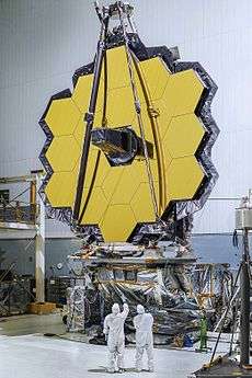
Optical Telescope Element is a sub-section of the James Webb Space Telescope, a large infrared space telescope to be launch in 2018.[1] The OTE consists of some major parts of the telescopes including the main mirror, the secondary mirrors, the framework and controls to support those mirrors, and various thermal and other systems to support the functioning of the telescope.[2] The other two major sections of the JWST are the Integrated Science Instrument Module (holds instruments) and the Spacecraft Element (SE), which includes the Spacecraft Bus and Sunshield.[3] The OTE collects the light and sends it to the science instruments in the ISIM.[4] The OTE has been compared to being the "eye" of the telescope and the backplane of it to being the "spine".[5] The main mirror system has an area of 25 square mirrors; it is a 3-mirror f/20 Anastigmatic design.[6] This yeilds an effective f/number of f/16.67 and focal length of 131.4 meters.[7][8] The main three-mirror telescope is a Korsch-type design,[9] and it feeds into the Aft Optics Subsystem (part of OTE), which in turn feeds into the Integrated Science Instrument Module which holds the science instruments and fine guidance sensor.
One part of JWST development was the production of the Optical Telescope Element Pathfinder.[10] The OTE pathfinder uses two additional mirror segments, and additional secondary mirror, and puts together various structures to allow testing of various aspects of the section, including Ground Support Equipment.[11] This supports the GSE being used on the JWST itself later on, and allows testing of mirror integration.[12] Another testbed was a 1/6th scale functioning version of the main mirror and technology, used especially to ensure the many segments can work as one.[13] Achieving a working main mirror was considered one of the greatest challenges of JWST development.[14]
The main mirror segments are aligned roughly using a course phasing algorithm.[15] Then for finer alignment, special optical devices inside NIRcam are used to conduct a phase retrieval technique, to achieve designed wavefront error of less than 150 nm.[16] To function as focusing mirror correctly the 18 main mirror segments need to be aligned very closely to perform as one.[17] This needs to be done in outer space, so extensive testing on Earth to ensure it will work is required.[18] To align each mirror segment, it is mounted to six actuators that can adjust that segment in 5 nm steps.[19] One reason the mirror was divided into segments is that it cuts down on weight, because a mirrors weight is related to its size, which is also one of the reasons beryllium was chosen as the mirror material, because of its low-weight.[20] Although in the essentially weightless environment of space the mirror will not weigh hardly anything, it needs to be very stiff to maintain its shape.[21] The Wavefront sensing and control sub-system is designed to make the 18 segment primary mirror behave as a monolithic (single-piece) mirror, and it does this in part by actively sensing and correcting for errors.[22] There nine distance alignment process that the telescope goes through to achieve this.[23] Another important aspect to the adjustments is that the primary mirror backplane assembly is steady.[24] The backplane assembly is made of graphite composite, invar, and titanium.[25]
The ADIR, Aft Deployable Infrared Radiator is a radiator behind the main mirror, that helps keep the telescope cool.[26] There are two ADIR's and they are made of high-purity aluminim.[27] There is a special black coating on the radiators that helps them emit heat into space.[28]
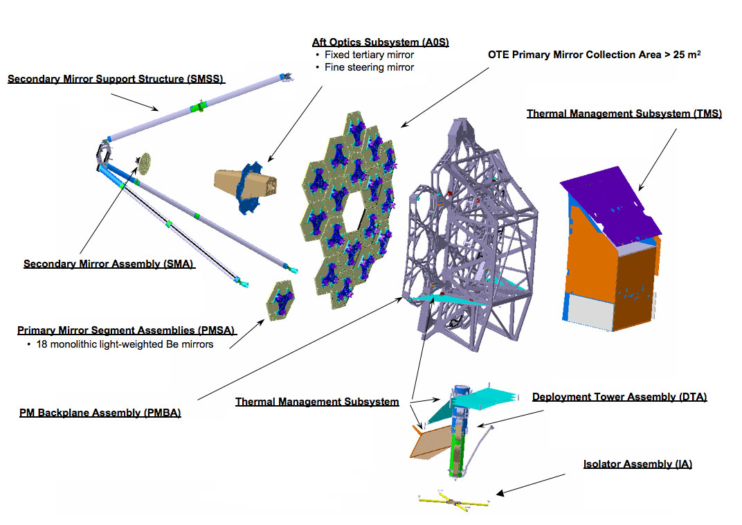
Parts of the OTE according to NASA:[29]
- Primary mirror (18 segments)
- Secondary mirror (74 cm diamater)
- Tertiary mirror (3rd) (in Aft Optics Subsystem)
- Fine Steering Mirror (in Aft Optics Subsystem)
- Telescope structure
- primary mirror backplane assembly
- main backplane support fixture (BSF)
- secondary mirror support structure
- deployable tower array
- Thermal Management Subsystem
- Aft Deployable ISIM Radiator (ADIR)
- Wavefront sensing and control
The Aft Optics Subsystem includes the Tertiary mirror and Fine Steering Mirror.[30] One of the tasks for the the Fine steering mirror is image stablization.[31]
Beryllium was chosen for a number of reasons including weight, but also for its low-temperature coefficient of thermal expansion compared to glass.[32] Other infrared telescopes that have used beryllium mirros include IRAS, COBE, and Spitzer.[33] The Subscale Beryllium Model Demonstrator (SBMD) was successfully tested at cryogenic temperatures, and one of the concerns was surface roughness at low kelvin numbers. [34] The beryllium mirrors are coated with a very fine layer of Gold to reflect infrared light.[35] There are 18 hexagonal segments that are grouped together to create a single mirror with an overall diameter of 6.5 meters (650cm, ~7.1 yards, ~256 inches).[36]
The Subscale Beryllium Model Demonstrator (SBMD) was fabricated and tested by 2001 and demonstrated enabling technologies for what was soon Christened the James Webb Space Telescope, previously the Next Generation Space Telescope (NGST).[37] The SBMD was a half-meter diameter mirror made from powered beryliium.[38] The weight of the mirror was then reduced through a mirror-making process called "light-weighting", where material is removed without disrupting its reflecting ability, and in this case 90% of the SBMD mass was removed.[39] Its was then mounted to a rigidly with titanium and underwent various tests.[40] This included freezing it down to the low temperatures required and seeing how it behaved optically and physcially.[41] The tests were conducted with the Optical Testing System (aka the OTS) which was created specifically to test the SBMD.[42][43] The SBMD had to meet the requirements for a space-based mirror, and these lessons were important to the development of the JWST.[44] The tests were conducted at the X-Ray Calibration Facility (XRCF) at Marshall Space Flight Center (MSFC) in the U.S. State of Alabama.[45][46]
The Optical Testing System (OTS) had to be developed to test the SBMD (the NGST mirror prototype) under cryogenic vacuum conditions.[47] The OTS included a WaveScope Shack-Hartmann sensor and a Leica Disto Pro distance measurement instrument.[48]
Timeline
- December 2001, final results from the SBMD test published.[49]
- December 2015, half of the main mirror segments installed.[50]
- March 2016, Aft Optics Subsystem installed.[51]
See also
- Integrated Science Instrument Module (another major JWST section)
- Primary mirror
- Secondary mirror
- Segmented mirror
- James Webb Space Telescope timeline
- Cryogenics
References
- ↑
- ↑
- ↑
- ↑
- ↑
- ↑
- ↑
- ↑
- ↑
- ↑
- ↑
- ↑
- ↑
- ↑
- ↑
- ↑
- ↑
- ↑
- ↑
- ↑
- ↑
- ↑
- ↑
- ↑
- ↑
- ↑
- ↑
- ↑
- ↑
- ↑
- ↑
- ↑ [https://directory.eoportal.org/web/eoportal/satellite-missions/j/jwst
- ↑ [https://directory.eoportal.org/web/eoportal/satellite-missions/j/jwst
- ↑ [https://directory.eoportal.org/web/eoportal/satellite-missions/j/jwst
- ↑
- ↑
- ↑
- ↑
- ↑
- ↑
- ↑
- ↑
- ↑
- ↑
- ↑
- ↑
- ↑
- ↑
- ↑
- ↑
- ↑
External links
- hotlink to diagram
- Optics & Photonics : Optical Innovations in the James Webb Space Telescope by P. Daukantas (November 2011)
- Reddit AMA with OTE manager
- Task completion (all JWST not just OTE)