Ring circuit
In electricity supply, a ring final circuit or ring circuit (often incorrectly called a ring main or informally a ring) is an electrical wiring technique developed and primarily used in the United Kingdom. This design enables the use of smaller-diameter wire than would be used in a radial circuit of equivalent total current. The reduced diameter conductors in the flexible cords connecting an appliance to the plug intended for use with sockets on a ring circuit are individually protected by a fuse in the plug.
Ideally, the ring circuit acts like two radial circuits proceeding in opposite directions around the ring, the dividing point between them dependent on the distribution of load in the ring. If the load is evenly split across the two directions, the current in each direction is half of the total, allowing the use of wire with half the total current-carrying capacity. In practice, the load does not always split evenly, so thicker wire is used.
Description
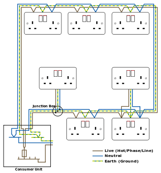
The ring starts at the consumer unit (also known as fuse box, distribution board, or breaker box), visits each socket in turn, and then returns to the consumer unit. The ring is fed from a fuse or circuit breaker in the consumer unit.
Ring circuits are commonly used in British wiring with socket-outlets to BS 1363. They are generally wired with 2.5 mm2 cable and protected by a 32 A fuse, an older 30 A circuit breaker, or a European harmonised 32 A circuit breaker. Sometimes 4 mm2 cable is used if very long cable runs (to help reduce volt-drop) or derating factors such as thermal insulation are involved. 1.5 mm2 mineral-insulated copper-clad cable (known as pyro) may also be used (as mineral insulated cable can withstand heat more effectively than normal PVC) though more care must be taken with regard to voltage drop on longer runs. The protection devices for the fixed wiring need to be rated higher than would protect flexible appliance cords, so BS 1363 requires that all plugs and connection units incorporate fuses appropriate to the appliance cord.
History and use
The ring circuit and the associated BS 1363 plug and socket system were developed in Britain during 1942–1947.[1] They are commonly used in the United Kingdom and to a lesser extent in the Republic of Ireland. They are also found in the United Arab Emirates, Singapore, Hong Kong, Beijing and Indonesia.
Pre-World War II practice was to use various sizes of plugs and sockets to suit the current requirement of the appliance, and these were connected to suitably fused radial circuits, the ratings of those fuses were appropriate to protect both the fixed wiring and the flexible cord attached to the plug.
The Electrical Installations Committee which was convened in 1942 as part of the Post War Building Studies programme determined, amongst other things, that the ring final circuit offered a more efficient and lower cost system which would safely support a greater number of sockets.[2] The scheme was specified to use 13 A socket-outlets and fused plugs, several designs for the plugs and sockets were considered. The design chosen as the British Standard was the flat pin system now known as BS 1363. Other designs of 13 A fused plugs and socket-outlets, notably the Wylex and Dorman & Smith systems, which did not conform to the chosen standard were used into the 1950s, but by the 1960s BS 1363 had become the single standard for new installations.
It has been claimed that the ring circuit was devised to combat the post-war copper shortage, but this is not supported by the textual record.
The ring circuit is still the most common mains wiring configuration in the UK, although the 20 A radial is also permitted by the Wiring Regulations.
Installation rules
Rules for ring circuits say that the cable rating must be no less than two thirds of the rating of the protective device. This means that the risk of sustained overloading of the cable can be considered minimal. In practice, however, it is extremely uncommon to encounter a ring with a protective device other than a 30 A fuse, 30 A breaker, or 32 A breaker, and a cable size other than those mentioned above.
The IET Wiring Regulations (BS 7671) permit an unlimited number of socket outlets to be installed on a ring circuit, provided that the floor area served does not exceed 100 m2. In practice, most small and medium houses have one ring circuit per storey, with larger premises having more.
An installation designer may determine if additional circuits are required for areas of high demand. For example, it is common practice to put kitchens on their own ring circuit or sometimes a ring circuit shared with a utility room to avoid putting a heavy load at one point on the main downstairs ring circuit. Since any load on a ring is fed by the ring conductors on either side of it, it is desirable to avoid a concentrated load placed very near the feed, since the shorter conductors will have less impedance and carry a disproportionate share of the load.
Unfused spurs from a ring wired in the same cable as the ring are allowed to run one single or double socket from each of the sockets on the ring (the use of two singles was previously allowed but was disallowed because of their being converted to doubles) or one fused connection unit (FCU). Spurs may either start from a socket or be joined to the ring cable with a junction box or other approved method of joining cables. Triple and larger sockets are generally fused and therefore can also be placed on a spur.
It is not permitted to have more spurs than sockets on the ring, and it is considered bad practice by most electricians to have spurs in a new installation (some think they are bad practice in all cases).
Where loads other than BS 1363 sockets are connected to a ring circuit or it is desired to place more than one socket for low power equipment on a spur, a BS 1363 fused connection unit (FCU) is used. In the case of fixed appliances this will be a switched fused connection unit (SFCU) to provide a point of isolation for the appliance, but in other cases such as feeding multiple lighting points (putting lighting on a ring though is generally considered bad practice in new installation but is often done when adding lights to an existing property) or multiple sockets, an unswitched one is often preferable.
Fixed appliances with a power rating over 3 kW (for example, water heaters and some electric cookers) or with a non-trivial power demand for long periods (for example, immersion heaters) are no longer recommended to be connected to a ring circuit, but instead are connected to their own dedicated circuit. There are however plenty of older installations with such loads on a ring circuit.
Criticism
The final ring-circuit concept has been criticized in a number of ways compared to radials, and some of these disadvantages could explain the lack of widespread adoption outside the United Kingdom.
Fault conditions are not apparent when in use
Ring circuits continue to operate without the user being aware of any problem if there are fault conditions or installation errors that make the circuit unsafe.[3][4]
| Fault condition | Observations |
|---|---|
|
|
|
|
|
|
Safety tests are complex
Testing ring circuits may take 5–6 times longer than testing radial circuits.[4] The installation tests required for the safe operation of a ring circuit are substantially more time consuming than those for a radial circuit, and DIY installers or electricians qualified in other countries may not be familiar with them.
Balancing required
Regulation 433-02-04 of BS 7671 requires that the installed load is distributed around the ring such that no part of the cable exceeds its capacity. This requirement is difficult to fulfill and may be largely ignored in practice, as loads are often co-located (e.g., washing machine, tumble dryer, dish washer all next to kitchen sink) at a point not necessarily near the centre of the ring.[4]
Can cause electromagnetic interference
Ring circuits can generate unwanted magnetic fields. In a radial circuit, the current flowing in the circuit must return through (almost exactly) the same physical path through which it came, especially if the live and neutral conductors are kept in close proximity of each other and form a twisted pair. This prevents the circuit forming a large magnetic coil (loop antenna), which would otherwise induce a magnetic field at the AC frequency (50 or 60 Hz).
In a ring circuit, on the other hand, it is possible, though unlikely, that the live and neutral currents are not equal on each side of the ring. Mains-frequency currents follow the path of least resistance, and it is possible, especially with ageing oxidised contacts, that from a socket, the lowest-resistance live connection is along the left-hand side of the ring, and the lowest-resistance neutral connection is along the right-hand side. As a result, current is flowing around the ring and will therefore induce a magnetic field.
See also
References
- ↑ Malcolm Mullins: The origin of the BS 1363 plug and socket outlet system. IEE Wiring Matters, Spring 2006.
- ↑ D.W.M. Latimer: History of the BS 1363and the ring circuit. Presentation papers from a public meeting to discuss the issue of ring circuits, IET, London, October 2007 (PDF in ZIP)
- ↑ Roger Lovegrove: EMC, April 2006
- 1 2 3 Roger Lovegrove: Ring circuits – the disadvantages. Presentation papers from a public meeting to discuss the issue of ring circuits, IET, London, October 2007 (PDF in ZIP)
- ↑ P Knowles: Ring main lining. EMC, February 2007