Schmidt corrector plate

A Schmidt corrector plate is an aspheric lens which is designed to correct the spherical aberration in the spherical primary mirror it is combined with. It was invented by Bernhard Schmidt in 1931,[2] although it may have been independently invented by Finnish astronomer Yrjö Väisälä in 1924 (sometimes called the Schmidt-Väisälä camera).[3] Schmidt originally designed it as part of a wide field photographic catadioptric telescope, the Schmidt camera, and is also used in other telescope designs, camera lenses and image projection systems.
Function

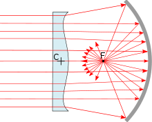
Schmidt corrector plates work because they are aspheric lenses with spherical aberration that is equal to but opposite of the spherical primary mirrors they are placed in front of. They are placed at the center of curvature "C" of the mirrors for a pure Schmidt camera and just behind the prime focus for a Schmidt-Cassegrain. The Schmidt corrector is thicker in the middle and the edge. This corrects the light paths so light reflected from the outer part of the mirror and light reflected from the inner portion of the mirror is brought to the same common focus "F". The Schmidt corrector only corrects for spherical aberration. It does not change the focal length of the system.
Manufacture
Schmidt corrector plates can be manufactured in many ways. The most basic method, called the "classical approach",[4] involves directly figuring the corrector by grinding and polishing the aspherical shape into a flat glass blank using specially shaped and sized tools. This method requires a high degree of skill and training on the part of the optical engineer creating the corrector.[4][5]
Schmidt himself worked out a second more elegant scheme for producing the complex figure needed for the correcting plate.[6] A thin glass disk with a perfectly polished accurate flat form was placed on a heavy metal pan. The upper edge of the pan was ground at a precise angle or bevel based on the coefficient of elasticity of the particular type of glass plate that was being used. The glass plate was sealed to the ground edge of the pan, then a vacuum pump was used to exhaust the air until a particular negative pressure had been achieved. This caused the glass plate to warp slightly. The exposed side was then ground and polished to a perfect flat. When the vacuum was released, the plate sprang back until its bottom surface was again plane, while the upper surface had the correct figure. Schmidt's vacuum figuring method is rarely used today. The glass plate will usually break if bent enough to generate a curve for telescopes of focal ratio f/2.5 or faster.[7] Also, for fast focal ratios, the curve obtained is not sufficiently exact and requires additional hand correction.
A third method, invented in 1970 for Celestron by Tom Johnson and John O'rourke[4][8] uses a vacuum pan with the correct shape of the curve pre-shaped into the bottom of the pan, called a "master block". This removes the need to have to hold a shape by applying an exact vacuum and allows for the mass production of corrector plates of the same exact shape.[5]
The technical difficulties associated with the production of Schmidt corrector plates led some designers, such as Dmitri Dmitrievich Maksutov and Albert Bouwers, to come up with alternative designs using more conventional Meniscus corrector lenses.[9]
See also
References
- ↑ Malacara, Daniel (1994). Handbook of Lens Design. New York: Marcel Dekker, Inc. p. 468. ISBN 0-8247-9225-4.
- ↑ Wright, Franklin B. (1959). "Theory and Design of Aplanatic Reflectors Employing a Correcting Lens". In Ingalls, Albert G. Amateur Telescope Making Advanced. Scientific American. pp. 401–409.
- ↑ telescopeѲptics.net, 10.2.2. - Full-aperture Schmidt corrector: Schmidt camera
- 1 2 3 METHOD FOR MAKING REPLICA CONTOUR BLOCK MASTERS FOR PRODUCING SCHMIDT CORRECTOR PLATES, United States Patent 3837124
- 1 2 Rod Mollise, Down with Love, uncle-rods.blogspot.com, Sunday, February 21, 2010
- ↑ Hodges, Paul C. (January 1948), "Bernhard Schmidt and his Reflector Camera", The American Journal of Roentgenology and Radium Therapy, 59
- ↑ Everhart, Edgar (May 1966), "Making Corrector Plates by Schmidt's Vacuum Method", Applied Optics, 5: 713–715, Bibcode:1966ApOpt...5..713E, doi:10.1364/AO.5.000713
- ↑ Tammy Plotner, universetoday.com, Celestron Telescope
- ↑ John F. Gills, Ph.D, From James Gregory to John Gregory - The 300 Year Evolution of the Maksutov-Cassegrain Telescope